Illuminating Innovation: A Journey of Light, Learning, and LEDs

The Spark of Inspiration

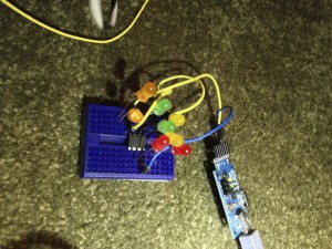
Ten years ago, standing on the corner of my property, I envisioned a project that would not only enhance the aesthetic appeal of my fence but also challenge my engineering skills. The idea was simple yet ambitious: to adorn each of the fence posts along the 600-foot boundary with clusters of WS2812B LEDs. The concept was to create a mesmerizing light display that could be seen from the two roads hugging our corner lot. However, I quickly encountered a significant hurdle—the signal stability of these LEDs over the 10-foot distance between each post.

Tinkering and Troubleshooting

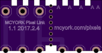
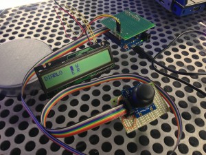
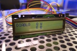
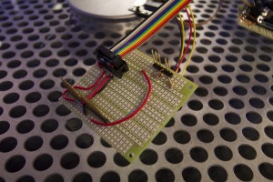
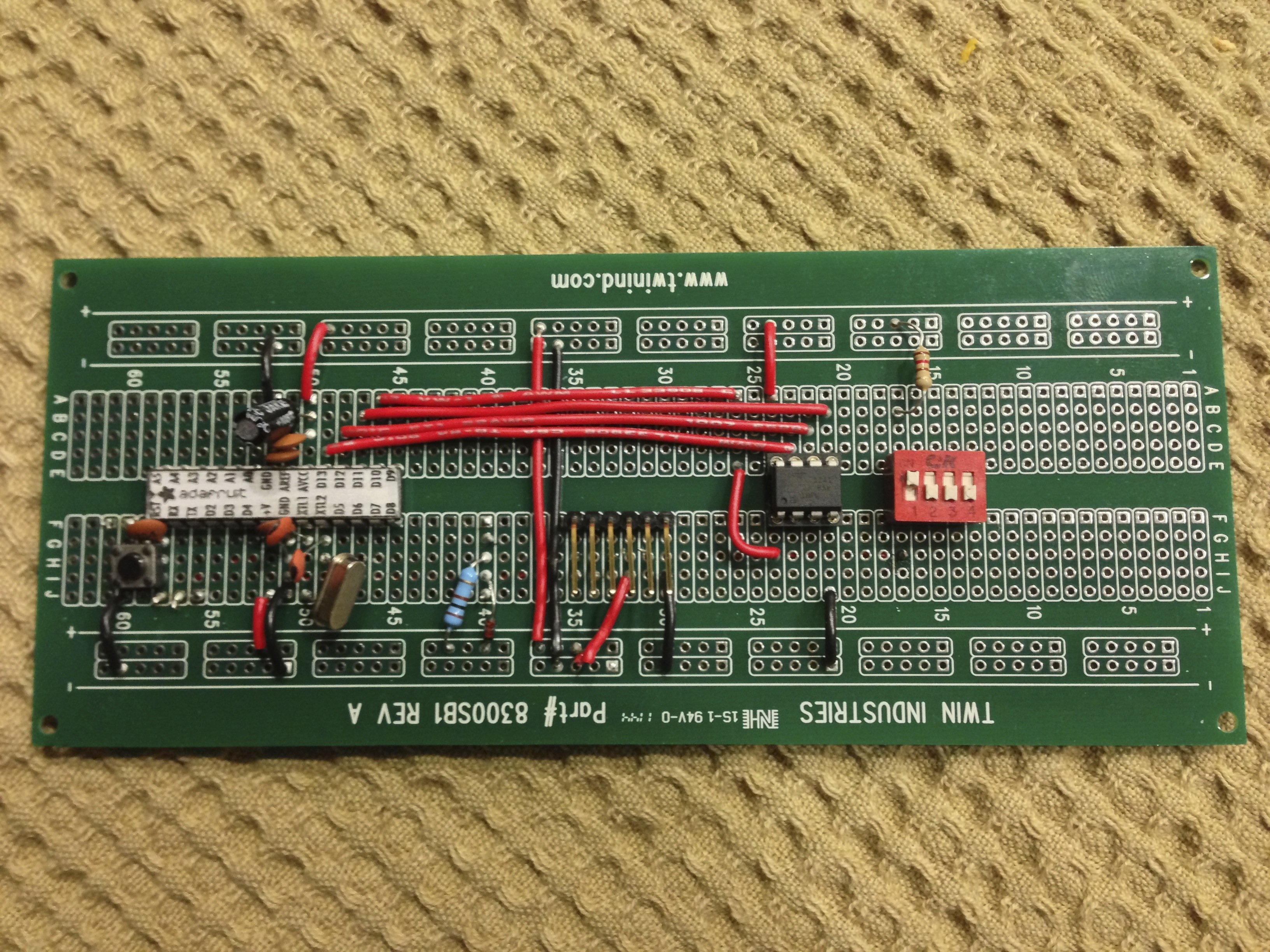
Undeterred by the limitations of WS2812B LEDs, I turned to RS485 chips, hoping their robust signaling capabilities could bridge the distances I was dealing with. The journey from prototyping boards at my kitchen table to designing and ordering custom PCBs was filled with soldering, testing, and more soldering. Yet, despite my efforts and enthusiasm, the results were far from what I had envisioned. Life, with its myriad distractions, eventually led me to shelf the project, leaving behind a trail of unfinished PCBs and unresolved challenges.

A Renaissance of Innovation

Fast forward to a December not long ago, a breakthrough in design software rekindled my passion for the project. This new tool not only allowed me to visualize my designs with ease but also offered PCB manufacturing and component assembly services. Suddenly, the daunting tasks of building and soldering were no longer barriers to progress. The ability to quickly iterate designs without the manual labor previously required was a game-changer. My project was back on track, evolving from its initial version to the more refined iterations of versions 2.0 through 2.3.

Refinements and Revelations

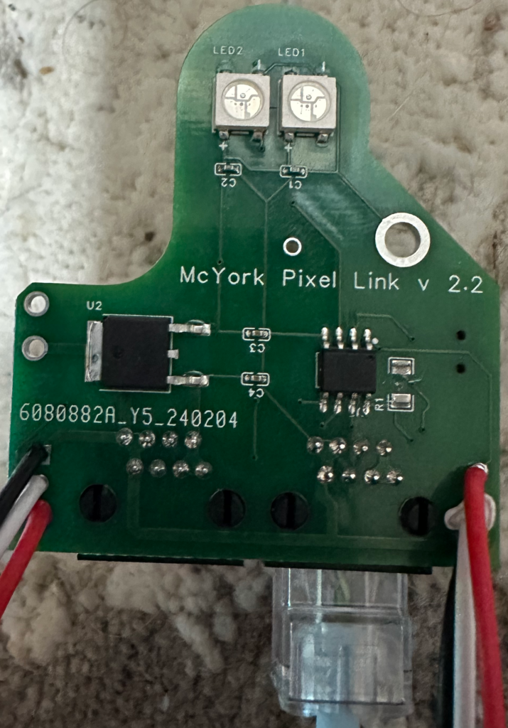
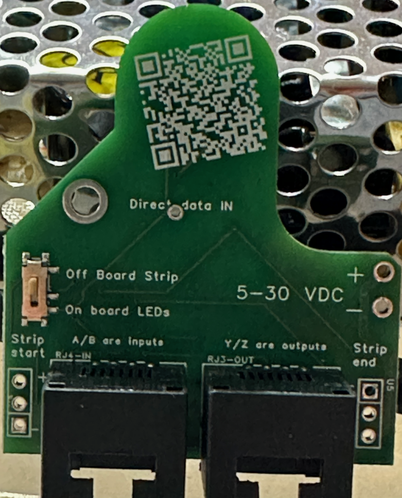
With each new version, my understanding of the project and its requirements deepened. The transition from a 10-pin RS485 chip to an 8-pin MAX490 marked a significant turning point, optimizing signal transmission without sacrificing speed. The addition of a switch for external LED connections and improvements in copper routing reflected my growing confidence and competence.

However, this journey was not without its setbacks. A lack of polarity and over-voltage protection led to several boards meeting their untimely demise—a stark reminder of the importance of incorporating protective measures in circuit design.

Looking Ahead: Version 2.4 and Beyond

As I await the arrival of version 2.3, with its enhanced power section and anticipation for the introduction of polarity protection in version 2.4, I reflect on the journey thus far. The path from a dream to a tangible, functional project has been fraught with challenges, learning opportunities, and moments of triumph.

This project, born from a desire to light up a fence line, has illuminated much more than that. It has been a journey of persistence, innovation, and continuous learning. As I look forward to further iterations and improvements, I am reminded that the process—the tinkering, troubleshooting, and iterating—is just as important as the final product.

To those embarking on their own DIY projects, remember that every setback is a setup for a comeback. Embrace the challenges, learn from your mistakes, and never underestimate the power of innovation and persistence.


Version 2.2 Onboard LEDs with off board capabilities (reb/white/black wires)
Top sode of version 2.2. Switch to change LEDs to On or Off board. Power input/Injector connection. Labled off board LED Start and End. Direct data (TTL) input when first board in the chain.

A10 Thunder VIP – well…

VIP Configuration Guide

Introduction

If you are setting up a test environment for an application, it is important to consider the “User Acceptance to Production” dilemma. This guide provides some basic tips on how to set up a VIP (Virtual IP) to ensure smooth deployment to production.

Test Environment

When setting up a test environment, always use port 443 (HTTPS) and never concede to having port 80 (HTTP) open. Although HTTPS can be a pain, it is essential to avoid setting up an HTTP path to the same resources on the test environment. This can create a dependency on HTTP that can cause problems in the future.

Redirections

If you want to provide HTTP access to the test environment, be careful when using redirections. Ensure they are “hard” redirects and you are not propagating the path and full URI. However, remember that something could go wrong even with the best intentions. Therefore, it is important to create hard errors that developers can see, which will provide the feedback necessary to prevent deployment issues.

Production Environment

When you go to production, force a port 80 HTTP redirection to the application’s home page (with NO path or query strings). This will not disrupt the application functionality, as port 80 HTTP was never available in the test environment.

VIP Configuration

To create a VIP, you must define and group servers for redundancy and scale. You can then apply a service group to a port of a VIP to get the whole picture. Here is a minimum VIP configuration:

slb server mcyork1 199.60.123.50
port 80 tcp

slb server mcyork2 199.60.123.51
port 80 tcp

slb service-group example-mcyork tcp
member mcyork1
member mcyork2

slb virtual-server example.mcyork.com 199.60.123.75
 port 80 http
  service-group example-mcyork

DNS Primer If you go to the IP 199.60.123.75, the result should be a response from either 199.60.123.50 or .51, where the website/application or API is hosted.

Conclusion

This is the most straightforward VIP configuration in any ADC/load balancer. Remember, no HTTP in pre-production – ever ( wait for the next example to see HTTPS in action). Follow these tips to ensure a smooth deployment to production.

Enjoy

A10 Thunder basic CLI

Step 1 – We are building a configuration to load balance a web service together. Won’t that be fun!

If you are new to the A10 ADC load balancer this may be interesting to you. If you use iRules with the F5 future steps may provide perspective. Experts in this area are encouraged to correct and enhance this content by emailing me ian@mcyork.com

That’s all for day one – exhausting right! Stay safe.

NeoPixel Link connector board

Building an array or grid of leds from Neopixel strips?  You might want one of these little boards I’ve come up with.  Here is a video (terrible) of me soldering together a few strips into a 3 x 42 array.  I found them to reduce the time and mistakes made when using individual wires.

 OshPark is where you can oder the boards.

Questions?  Please email me (ian @ mcyork.com)


What could you possibly use 8 relays on a board for?

I’ll be honest, today is payday and, I’ve been thinking about improvements to existing projects, surf’n the web looking to buy!  Then I thought of my binary Christmas tree display.  I remember seeing an 8 relay board on the web a long time ago, and thinking what could I use THAT for?  I had to come up with an excuse to buy it of course.  I convinced myself I could build a holiday light display with a twist.  I decided I’d flash the lights in binary.  Check it out if you have not watched it yet.

Now that was a fun project.  How do I expand on that in the context of “the farm”.  There’s a solar array in the field  – ideas?

I can’t say I bought this one below – but they all look about the same.  When you are just having fun with an Arduino you can afford the 8 pins to drive these things.  I suspect some have a BCD to relay decoder chip built in.  That would reduce the number of pins you need to dedicate.  Or you can use a shift register (those are fun. Look em up if you have not considered them in your project yet).


5V Eight 8 Channel DC 5V Relay Switch Module for Arduino Raspberry Pi Arm AVR | eBay

So now you’ve got a project for yourself to figure out.  The code for an Arduino to do the above binary tree display was fairly simple.  You can get fancy if you want.  Where you’ll want to be careful is how you wire up the high voltage side of the system.  I took a lot of care modifying a power strip.  This had the advantage of 8 sockets ready to plug into.  Go for it – be safe.

The keyboard helper

I was talking with a friend who has a big problem.  His son can’t use a keyboard but loves to play computer games.  He can only use a mouse and only with his right hand.  He has very limited abilities in his left.  It became clear after our conversation that if we put our heads together we could make something that might enable him to play the different computer games with more ease and enjoyment.

New video link added at the end of this posting.

We imagined a joystick that could be used to maybe send different keystrokes to the keyboard via some device.  I took this problem home and below is what became “the keyboard helper”.

KeyHelper1

The Leonardo has a great capability; It can emulate a keyboard and mouse.  Using this as the core of the new device I tested a number of code snippets   I was able to send words and keystrokes to Notepad, what fun!  The next thing was to read analog ports connected to a joystick.  There are a ton of examples on the web, I got this running quickly.  To wire up the joystick I needed to tie in some resistors.  I’ll try to explain why they are on the circuit later.  The last part was to add an LCD display for some visual feedback.  I thought it would be important and we found out after the fact that it ended up having a very different function than what I had first envisioned.  LCD displays can be hooked up in a few different ways the most common are parallel (all pins) or via some type of intermediate device that you to talk to via a serial or i2c interface.  I had an i2c to LCD kit from an old project and decided to re-use this (the link is to a more recent iteration).  The LCD display itself was pulled out of an old PBX phone, it had some odd pinouts but normal LCDs you find on the web will be simple to wire up.

On a 2 hr flight, I crafted most of my notes on how I felt the “system” would work.

KeyHelper5

I’d present a grid on the 2 line display of the characters Q W E R.

________Q__W______

________E__R_______

Something like the above. When you tell the LCD to use a blinking cursor and then move to a position on top of a letter – it looks selected.  By moving the cursor over each letter as the joystick moves – you can see what letter is available to be typed to the computer.  Great visual feedback.  In the above diagram suppose Q is high lighted.  The movement UP or LEFT on the joystick would then send the letter Q to the keyboard.  A movement DOWN would select E but not send E.  Once on E a movement LEFT or DOWN would send E to the keyboard.  Scroll to the letter needed then move -off- the screen to send it to the computer.

KeyHelper6

That’s how the 1.0 version functioned. There was some immediate feedback as the game being played changed.  It would be preferred to hold the key down and not just type one letter.  Selecting the letters became less critical as now it was a matter of just holding down the key and there were only 4 to send.  Here is the resulting logic main loop of the program that shows this modified approach.

void loop()
{
 center = 1; 
 up = map(analogRead(0),0,1023,0,1);    // Q MoveTo(0,9); 
 left = map(analogRead(1),0,1023,0,1);  // E MoveTo(1,9); 
 down = map(analogRead(2),0,1023,0,1);  // R MoveTo(1,11);
 right = map(analogRead(3),0,1023,0,1); // W MoveTo(0,11);

 if (up) {
 Keyboard.press('q');
 MoveTo(0,9);
 center = 0;
 }
 if (left) {
 Keyboard.press('e');
 MoveTo(1,9); 
 center = 0;
 }
 if (down) {
 Keyboard.press('r');
 MoveTo(1,11);
 center = 0;
 }
 if (right) {
 Keyboard.press('w');
 MoveTo(0,11);
 center = 0;
 }
 if (center) {
 Keyboard.releaseAll();
 MoveTo(0,0);
 }
}

The letters are now being sent as lower case. What’s nice about this approach is the MAP function.  It has a lot of uses.  Here it converts the range 0 to 1023 into the range 0 to 1.  This enables the code to read both momentary switch type joysticks or analog potentiometer joy sticks (we’ve used both in our prototypes).

Mental Note: if two states are on at the same time does the keyboard function send both or does the last one sent win?  Think to move on a diagonal in a game and how the code above may or may not enable this.

I am working on a wiring diagram it is going to be a while until I either build a second version or I can borrow back the one I’ve built for a day to recall the exact details.  Like I said above – examples for each element of this are easy to find on the web – you should not have much trouble.

A working version of the code (assuming you use the right pins with your LCD and such) is here.  As my LCD and I2C are probably different from yours – there will need to be some adjustments in the commands sent to the LCD (maybe).

I liked this project for a number of reasons.

  1. Jerry is a much happier camper now. UPDATE BELOW
  2. I had no idea how great that would make me feel.
  3. Game control is vastly improved.
  4. The project was small in scope and I was clear on the goal.

Thank you for reading.  There is not too much more to say about this project at this time.  It will be a while but the circuit will be doodled up some day.

Go make stuff.

The LCD took on an unexpected use:  It happens that the joystick needs to be positioned just right.  Exactly right.  Such that the limited motion of the left hand can move in the 4 directions.  It takes some time to get this center point just right.  The LCD will be highlighting the direction of the “problem” and my friend can use this as visual feedback until he gets both the joystick and hand centered.

UPDATE. The fine film crew at work put together this video of the project’s impact.


Chip programmer with a twist

I am working on 1000 projects all the time.  You may already know that of me.  This one will be a fun adventure.  I’ve started by shrimping.it this is a site where they show you how to build a bare-bones Arduino.  I went and ordered the part for 4 kits via the electronics seller http://www.taydaelectronics.com/ it was under $30 for all the parts I needed.  I did not get boards as I plan to design my own at a later phase. Shrimp + SPI to 8 pin chip  Here’s the shrimp built with an 8 pin chip holder where it can be used to program the little chip.  This is an Atmel ATTiny 85 ready to be programmed.

Now the hard part.  Let’s say I want to program a lot of these little chips.  Wouldn’t it be nice if the Arduino held in memory all the code and capabilities to program the chip without an attached USB link to a computer?  That’s goal #2.

random blickers

Here is an ATTiny 85 running code that was pushed through the Arduino in the traditional manner (Goal #1).  What I like about the Tiny line of chips is there is little to no supporting hardware required to have them run.  This makes them a lot of fun for all kinds of little builds.  They will even run off three or 4 AAA batteries and for quite some time.

Stock Bot to Arduino

The original StockBot was built on the Netduino platform.  I’ve been working on the code for the Arduino platform and have now assembled working code.  I can’t claim it is stable yet but it’s doing the job for now.

I am using the Ethernet Arduino.  As I explore a number of things all the time, I have also made a shield for the Arduino to see if this project could become a kit for others to build.  A little stuck on a source for Numitron tubes so I am trying to make the board generic enough to take a tube or a normal led display (still puzzling that through).

Let me clean up the code – I’ll take a hard look at it over the next month.  Maybe after the skis hit the slopes in Whistler I’ll have something to post and walk everyone through. Early December if you don’t ski or board.

What’s StockBot – here’s the beginning post

Here are the prototype boards I had made.  They have a nasty bug but I learned something (and could fix it so all is good).

Lots of LEDS – now I get it!

This is the page that allowed me my “Eureka” moment on how to drive a large number of outputs from a very few number of pins.  If you ever wished you could have 10 or a 100 more output pins – the shift register chips are ones to consider.  I won’t blabber on just follow the link watch the video and you know where to start if it can be applied to your own effort.

http://bildr.org/2011/02/74hc595/ 

Enjoy

Stock Bot – about the 4511 BCD to 7-segment decoder

Not to be trite but you may learn more here wikipedia.org, than here.  This post is intended to fill in some of the background of how the 4511 chip was used in the Stock Bot project.  Let’s dive in and see if it remains coherent.  The chip is designed (I presume) to enable one to use fewer data lines to drive a 7-segment display.  LED displays are common while the one in Stock Bot is a little less so.  A seven segment display has 7 inputs one for each light element.  You would need 7 data lines to drive a single digit and much more to drive additional digits.  This project does not use the data latching features that enables several 4511 chips to drive several digits while keeping the data line count to a minimum.  When you scale the number of digits you really save on data lines and the value of the chip becomes evident quickly.  To be brief, several digits can be managed (like a clock) by locking the currently displayed value into each chip and then unlocking only one digit at a time to effect a change to that digit.  Quickly locking and moving on, unlocking change lock, continue.  If that made any sense you got the idea.  Do this fast enough and large multi-digit displays can be managed – again with 4 data lines and the latch control logic.

Driving the single chip was a fun code experiment.  So let’s look at that.  Like I said on the Stock Bot page I had to learn (re-learn/hack in) C# for this.  When you drive the chip you are essentially sending it a binary code along 4 digital lines.  A 4 line data bus I guess.  Given an integer from 0 to 9 convert, that to binary or otherwise figure out how to set your 4 data pins correctly.

A set of if statements would do that.  A switch statement would do that.  Both I tried as I had to get something started.  Neither felt clean enough to me (don’t get me wrong some of the code is still too ugly to even tell you about yet/ever).  So I worked out what I have below because I knew in my mind something cleaner should exist.  Your improvements are welcome as comments.

    // helper class
    class BCDOutputClass
    {
        byte mask1 = 1;
        byte mask2 = 2;
        byte mask3 = 4;
        byte mask4 = 8;

        OutputPort Bin1 = new OutputPort(Pins.GPIO_PIN_D9, true);   // A
        OutputPort Bin2 = new OutputPort(Pins.GPIO_PIN_D12, true);  // B
        OutputPort Bin3 = new OutputPort(Pins.GPIO_PIN_D11, true);  // C
        OutputPort Bin4 = new OutputPort(Pins.GPIO_PIN_D10, true);  // D
        OutputPort CommaPin = new OutputPort(Pins.GPIO_PIN_D13, false);

        // Constructor
        public BCDOutputClass()
        {
            //
        }

        // Instance Method
        public void Display(byte a)
        {
            a = (a < 10)? a : (byte) 10;
            Bin1.Write((a & mask1) > 0);
            Bin2.Write((a & mask2) > 0);
            Bin3.Write((a & mask3) > 0);
            Bin4.Write((a & mask4) > 0);
        }

        public void Clear()
        {
            Display(10);
            Comma(false);
        }

        public void Comma(bool a)
        {
            CommaPin.Write(a);
        }

        // Destructor
        ~BCDOutputClass()
        {
            // Some resource cleanup routines
        }
    }

Most of this becomes clear if I just talk about the meat of the code in public void Display(byte a).  Maybe not but let’s start there as it is the crux of what makes this (IMHO) better over an if or switch statement.  I have, of course, not tried to figure out if this compiles to smaller code or not – that’s not a concern I have any interest in yet.

The function takes in a byte – the code when running sends in the values zero to 10 when all is normal.  10 is an exception and I should explain that first as the line first executed is a test for values over 10 and if over we revert a to 10. 10 in binary is 1 0 1 0.  Setting the 4 pin data bus to an invalid value.  1 0 1 x (where x means it’s not important) happens to BLANK the display.  This makes the code in the function public void Clear() fairly obvious now why it sends a 10 to Display().

The 4 pins how do they get set?  ok, let us use the digit 9 and now step through the rest of the function.  Pin 9 on the Netduino is connected to A or D0 on the 4511, the lowest order bit (ones). 12 is to B or the twos, 11 is to C or the fours and pin 10 to D the highest order bit the eights.  You can look to the mask declarations to get a feel for the positions too.

9 is binary 1 0 0 1

We need to set line A to true, line B to false, line C to false and line D to true.

(a & mask) what does that do?  “a” is type byte and mask1 is of type byte.  The & says do a bitwise AND of the two values.  What’s a bitwise and – (for now – Google it) but I’ll do the math here and might get it across.

1 0 0 1  (9)
0 0 0 1  (mask1)
-------  bitwise and says 1 only when all are one
0 0 0 1 (1)
Result = 1

1 0 0 1  (9)
0 0 1 0  (mask2)
-------  bitwise and says 1 only when all are one
0 0 0 0 (0)
Result = 0

1 0 0 1  (9)
0 1 0 0  (mask3)
-------  bitwise and says 1 only when all are one
0 0 0 0 (0)
Result = 0

1 0 0 1  (9)
1 0 0 0  (mask4)
-------  bitwise and says 1 only when all are one
1 0 0 0 (8)
Result = 8

Let’s take the results of the first operation.  We got a 1.  There’s more in that line of code (a & mask1) > 0

Greater than zero completes a comparison.  Results in a boolean.  True or False.  The first part will result in a zero when we need a false result and a true value when the result is anything else 1 or above.  In the case, we just ran through, we had a 1 and an 8, both greater than zero, and so had two lines (the first and last) set to true.

By now you’ve either gone Aha! or Duh or are scratching your head.  Either way I am done for now 🙂 enjoy.