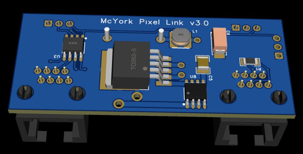
Welcome to the Pixel Link v3.3 home page. Below are instructions on how to wire these up and why you’d want them.
Wiring up the device
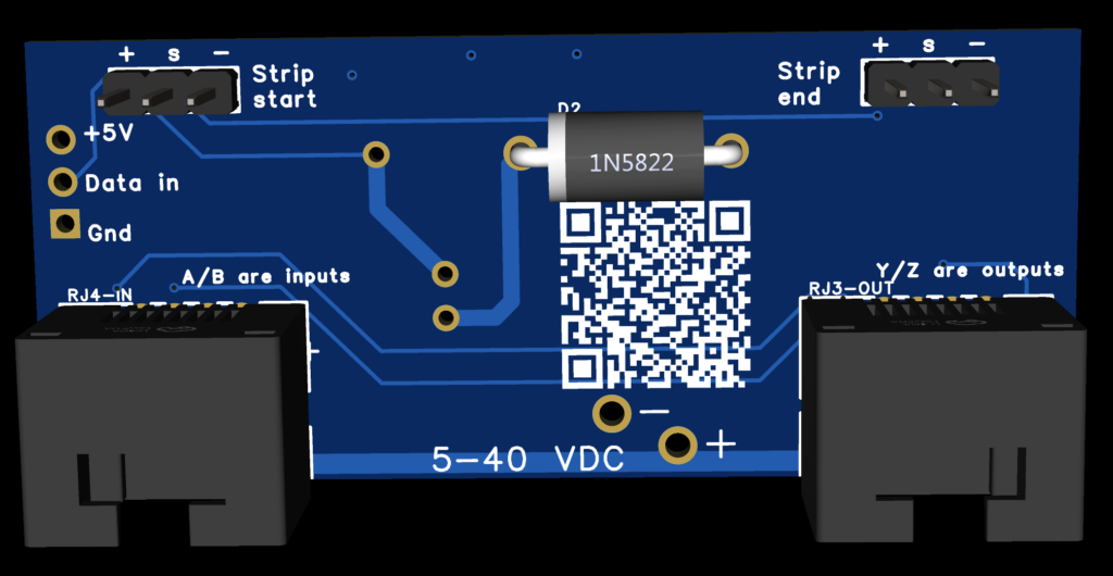
We will call this view the top view. This is the image referenced in all the text below when saying left, right, etc.

Note: The Strip connections are not populated with the header pins.
The board is tested with the WS2812B LEDs and strips.
There are two primary methods for wiring these boards: “the first board” and “the rest of the boards” in the chain. We’ll begin with the setup for “the rest of the boards,” as it is more straightforward.
For most boards in the chain, the RJ45 connector on the left serves as the input, receiving data from another Pixel Link board. The RJ45 on the right facilitates the connection to the subsequent board in the chain.
Next, attach connectors to the Strip start and end holes, avoiding the use of the far-left vertical orientation holes labeled +(5v), s(data), and -(ground). The functions of the far-left +5v, Data in, and Gnd holes, along with the larger – and + in the middle bottom, will be explained later.
Here is a link to an Amazon list related to this project. It includes items I have used as connectors, power supplies, etc.
Connect a standard WS2812B string to the Strip connectors’ -, s, and + lines, where ‘s’ represents the data or signal line. It’s important to note that there is no default internal connection between the s(data) lines, meaning the board will not transmit the signal further without at least one connected LED.
You can bridge (J1 solder bridge) the two “s” connections if necessary, for instance, if a string of LEDs fails or extends beyond the distance between boards. See below for the more common use case.
For the first board in the chain, which may or may not have local LEDs and is located near the project compute, WS2812B signal, and main power supply but far from the first LED effect/string:
To drive LEDs on the first board, use the left-hand side connectors labeled +5v, Data in, Gnd to input the signal into the board, through any connected LEDs, and onward to the next board. Use the right RJ45 to continue the chain to the next board. The left RJ45 will remain unconnected.
Powering the board(s) requires using the two middle bottom holes labeled—and + with a voltage range of 5 – 40 VDC. Once powered, the onboard regulator has no problem providing a stable 5-volt supply suitable for small Arduino-like boards. So, in such a case, the left-hand side connectors labeled +5v and Gnd send power to your project, and the ‘Data in’ is the signal you send to the board.
If the first board is placed without active LEDs, you can bridge s to s using the J1 solder bridge. Alternatively, if you have soldered connectors to the board, they may be able to be connected to each other. This configuration might complicate things if power/signal from another board is introduced via the input RJ45. So keep in mind that when you are originating a signal on ‘Data in,’ the left side, RJ45 should not be used.
Power considerations are crucial due to potential issues with voltage drop over distance. Pixel Link addresses this with several features:
The onboard DC/DC converter can supply 3 Amps at 5 volts, supporting a significant number of LEDs per node under most conditions. However, actual power efficiency will be evaluated with further testing involving multiple boards and LED configurations.
For connectivity, standard ethernet cables are used because they are available in long lengths. Six wires are dedicated to power—three each for positive and ground. Future testing may necessitate a redesign for a larger gauge wire. The math already suggests I need to rethink the copper to use 2oz thickness and wider traces—that alone will not account for the RJ45 to RJ45 current running in local traces.
The design aims to efficiently support numerous boards over extensive distances by utilizing a regulator capable of handling up to 40 Volts. This approach minimizes voltage drop issues and allows flexible power injection points along the chain.
After experiencing issues with reverse polarity leading to damage, reverse polarity protection was added to each board. This feature will be tested in the upcoming version 3.3 boards.
It is crucial to remember that these boards are not compatible with standard ethernet equipment. Connecting them to routers, computers, or network gear could result in damage.
Why Pixel Link
Pixel Link offers a powerful solution for those looking to use WS2812B addressable LEDs across long distances. “Long” in this context means up to 4000 feet theoretically, thanks to its transceivers. However, achieving connectivity over 1000 feet is not only possible but has also been a key focus of our testing.
These boards are versatile across various applications. For instance, envision illuminating every fence post across a property with colorful, programmed LEDs—a challenging goal with sixty-six posts, yet a clear demonstration of Pixel Link’s capabilities.
For large-scale art installations requiring programmable lighting across different areas, Pixel Link is the perfect fit. It also offers an enhancement for those intricate Christmas light displays that have grown in popularity, adding a new layer of sophistication and scale.
This technology isn’t just for large or temporary setups; it’s also ideal for permanent installations that aim to incorporate innovative lighting. Although designed primarily for WS2812B LEDs, the board is compatible with other devices using the same one-wire protocol, such as full-color floodlights operating on the WS2811B protocol.
What distinguishes Pixel Link is its ability to transmit TTL signals over significant distances. This feature isn’t limited to lighting; any data following the protocol can be sent across this platform. With a bandwidth minimum of 800kbs and potential peaks up to 2.5Mbps, the possibilities for innovation are extensive.
Looking ahead, Pixel Link represents a leap forward in technology, pushing users to expand the limits of their projects. It opens new doors for both enthusiasts and professionals, fostering the creation of immersive environments and dynamic installations. With Pixel Link, the future of programmable lighting is within our grasp, heralding an era of unmatched creativity and connectivity.
What Next
This version 3.3 board is almost ready to be manufactured in a very small batch for testing. After that order, I’ll know more about the per-board cost. Two boards are the minimum as an injector board without LEDs and a ‘distant node’ board to solve that distance problem. One board alone can drive LEDs and be a power regulator but won’t have any next node to send data to.
There’s a back story of how I got here from there, but it’s TL;DR even for me. There’s a post here of some of that.